![]()
  |
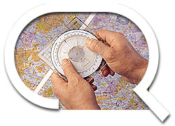
The operational simplicity
of QuDieM NAVIGATOR is illustrated below.
Planning
a VFR Flight or Diversion
 |
|
  |
|
 |
|
|
|
|
|
|
and
|

|
|
STEP
6 |
|
|
STEP
7 |
|
|
Note that where the wind is within ±10° of the flight track/course, the arithmetic application sign is determined by the direction from which the reference mark was aligned in step 6. In practice unless wind speed is above 25kts compensation for wind angles of less than 10° is marginal. |
|
|
|
NB. Completion of Steps 1 & 2 above is an essential preparation for any use of the instrument. Good airmanship requires accurate tracking of planned radials and flight times. Whether "beacon bashing" or navigating with GPS, an appreciation of the wind correction for both heading and ETA is essential. In each of the following applications, the completion of Steps 6 & 7 above conveniently provides the required information. The centre aperture of QuDieM Navigator has been designed to match the VOR compass rose printed on half-mill charts to facilitate alignment with such beacons. Tracking
From a VOR |
|
|
|
Tracking
To a VOR NDB
Radials Holding
Patterns |
|
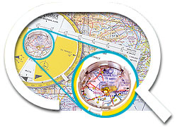
Where am I?
|
|
1. Determined your magnetic bearing to a suitable beacon from the cockpit instrument. 2. Align the instrument over the beacon with the bearing arm at minimum distance and rotate the bearing arm to set the °M From Target pointer to this bearing on the magnetic (yellow) compass. 3. Insert a marker into the target aperture and, whilst preventing any rotation of the instrument, draw a line on the chart by extending the bearing arm using the marker. 4. Repeat the procedure with a suitable second beacon. The point of intersection of the lines will indicate your present position. Aircraft equipped with DME can locate their position using a single beacon and twinned with DME by setting the bearing arm to the indicated distance from the beacon. Having aligned the instrument over the reference beacon as 1 above, the target aperture will indicate their present position. |